
The fundamental principle of any imaging lens, whether in conventional light optics or electron microscopy, is to manipulate the trajectories of incident radiation, causing them to converge at a focal point.
In an electron microscope, this function is performed by electromagnetic lenses, which are typically comprised of precisely wound solenoidal coils. These lenses generate strong, axially symmetric magnetic fields that are used to control the trajectories of a high-energy electron beam, thereby forming a magnified image of a specimen.
The focusing action is governed by the Lorentz force. An electron traveling perfectly along the central optical axis of the lens experiences no net force, and its path remains undeflected. However, for paraxial electrons—those traveling parallel to but displaced from the axis—the interaction with the magnetic field is non-zero. The Lorentz force, described by the vector cross product F = q(v × B), where q is the electron charge, v is its velocity, and B is the magnetic field vector, is exerted on these electrons. This force acts perpendicularly to both the electron’s velocity and the magnetic field lines.
The resultant force compels the electrons into a helical trajectory, causing them to spiral around the optical axis. The net effect of this motion is a convergence of the electron paths. A beam of electrons that is initially diverging from a point on the specimen is thus made to converge to a corresponding point in the image plane. This action is functionally analogous to a conventional convex glass lens, which refracts diverging light rays to form a focused image.
Magnification and the Lens Equation
Within the framework of geometric optics, the transverse magnification (M) of a lens is quantified as the ratio of the image distance (v) to the object distance (u):
$$
M = \frac{v}{u}
$$
Here, u represents the distance from the object to the principal plane of the lens, and v is the corresponding distance from the principal plane to the conjugate image plane.
The relationship between these distances and the intrinsic focal length (f) of the lens is rigorously described by the thin lens equation:
$$
\frac{1}{f} = \frac{1}{u} + \frac{1}{v}
$$
A key principle in electron optics is that this classical formalism is directly applicable to the behavior of electromagnetic lenses. Consequently, these equations provide the fundamental mathematical framework for characterizing the performance of each constituent lens within the electromagnetic column. They are essential for calculating the overall magnification of the instrument and for determining the precise lens excitations required to achieve focus.
Components of an EM Lens system
A functional electromagnetic lens assembly within an electron microscope is a sophisticated system comprising several key components, each with a distinct role in shaping and correcting the electron beam.
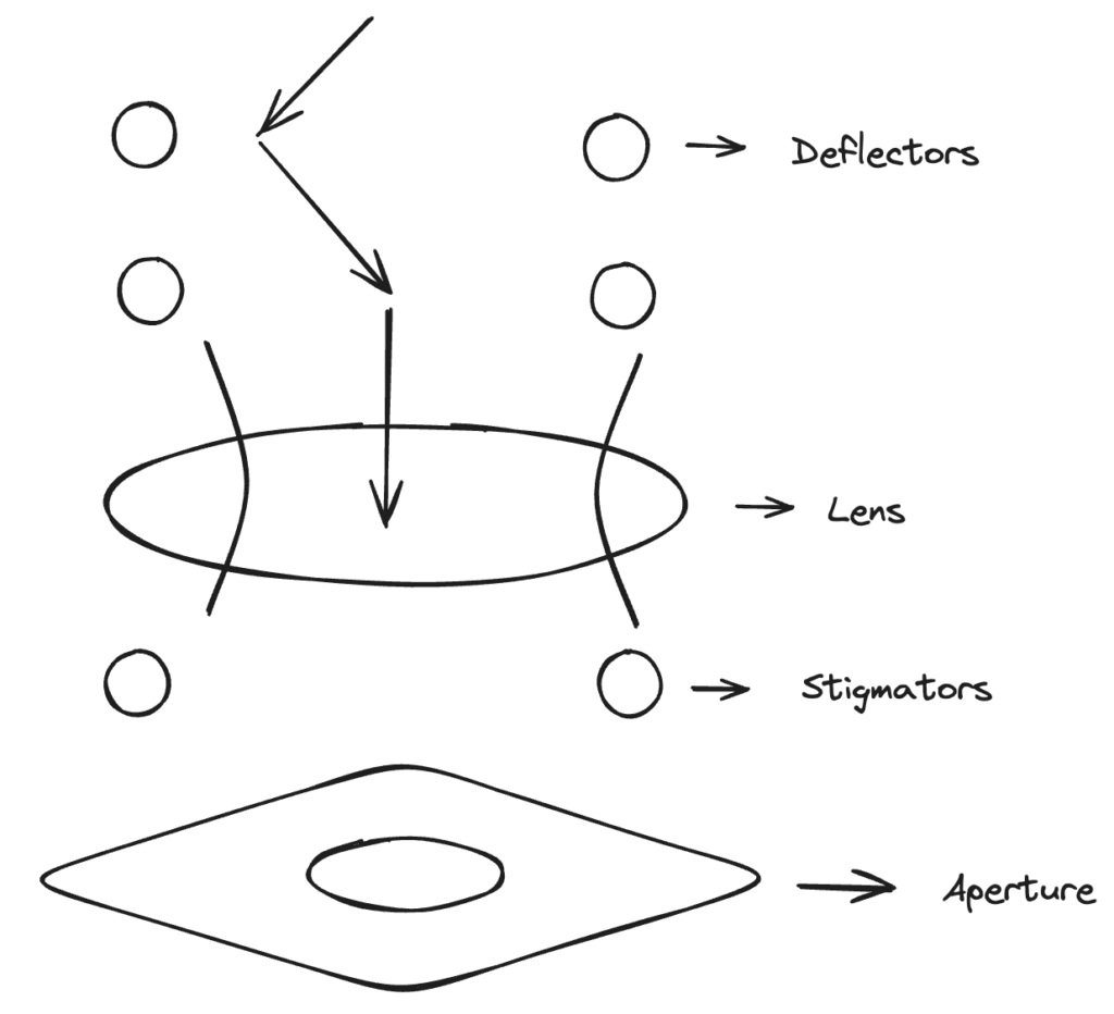
1. Primary solenoidal coil
The core of the lens is a precision-wound solenoidal coil encased within a soft iron shroud and pole piece. When energized by a highly stable, regulated current, this coil generates a strong, axially symmetric magnetic field concentrated within a narrow gap. This field constitutes the principal refractive element of the lens, responsible for imparting the focusing power necessary to converge the electron beam.
2. Beam deflection coils
Integrated within the lens assembly are orthogonal pairs of deflection coils (dipole correctors). These auxiliary coils generate controlled magnetic fields perpendicular to the optical axis. Their function is to precisely manipulate the beam’s trajectory to correct for both:
- Angular misalignment (tilt): Ensuring the electron beam propagates perfectly parallel to the defined optical axis.
- Translational misalignment (shift): Ensuring the beam passes directly through the magnetic center of the lens.
These correctors are essential for compensating for misalignments arising from factors such as thermionic source drift or minor mechanical inaccuracies in the column assembly.
3. Stigmators
Ideal rotational symmetry of the magnetic field is often compromised by practical factors, such as minute inhomogeneities in the pole piece material, machining tolerances, or parasitic fields. These asymmetries induce astigmatism, a critical lens aberration characterized by a focal length that varies with the azimuthal angle. To counteract this, stigmators—typically multipole elements like quadrupoles and octupoles—are incorporated. These elements superimpose a weak, non-axially symmetric field of adjustable magnitude and orientation onto the main lens field. By carefully tuning the stigmator, the primary astigmatism can be nullified, restoring the rotational symmetry of the lens’s focusing action.
4. Aperture
Typically positioned at a back focal plane within or subsequent to the lens, a physical aperture (a thin metallic disc with a central orifice) serves as a crucial spatial filter. It physically intercepts electrons scattered at high angles relative to the optical axis. This selection process is critical for:
- Reducing the effects of lens aberrations, particularly spherical aberration, which is strongly dependent on the electron’s angle of deviation.
- The aperture thus defines the acceptance angle of the lens, permitting only those electrons within a small, well-defined solid angle to contribute to the formation of the final image.
- Enhancing image contrast by removing inelastically scattered electrons.